What is Filament Winding? A Visual Guide for Engineers
A Type IV 700-bar hydrogen tank for a fuel-cell truck has a structural shell that reads, on a spec sheet, as a 2–3 mm polymer liner with a 25–35 mm carbon/epoxy laminate wrapped around a 350–500 mm cylinder closed by ellipsoidal domes. That laminate is filament wound. It starts and ends as a single continuous carbon tow being laid onto a spinning mandrel by a moving carriage. For closed, oriented-fibre shells at that wall thickness and production volume, filament winding remains one of the main manufacturing routes.
The same process is used for SCUBA tanks, CNG bus tanks, solid-rocket motor cases, composite-overwrapped pressure vessels (COPVs) for satellites, drive shafts, and many pipe or tubular composite products. Related winding and wrapping methods also appear in selected wind-energy and industrial structures. It has been in industrial use since the 1940s. What is new is the demand: the hydrogen economy, electric vertical take-off and landing (eVTOL) aircraft, and the next generation of launch vehicles all pull on the same supply of high-performance filament-wound shells.
This is the visual primer — what filament winding actually is, what every word in that opening paragraph means, and what an engineer should look at before spec'ing, buying or designing a wound part. A live 3D simulator runs alongside in the browser, no install or CAD package required.
Why this matters now
For most of the last fifty years, filament winding sat quietly inside aerospace and industrial gas. Two things changed that in the last five years.
Hydrogen mobility. A Type IV 700-bar tank for a fuel-cell truck typically uses 20–30 kg of carbon fibre per kg of stored hydrogen. Global hydrogen-mobility roadmaps imply large tank volumes by the early 2030s, and Type IV high-pressure storage is commonly built around filament-wound carbon/epoxy overwraps.
eVTOL and small launch. Lightweight COPVs for cold-gas thrusters, propellant tanks, and pressurised airframe components are all wound. The cost-per-kg target is set by the airframe, not by legacy aerospace pricing, which is pushing producers toward higher automation and tighter process control.
Wind turbine roots and large pipes. Large pipes and selected highly loaded tubular or insert-like structures use winding for the same reason hydrogen tanks do: you can place fibres close to the load path in a repeatable, low-scrap process.
In every one of these markets the binding constraint is the same: the engineering team has to understand what the process can and cannot do before they can spec the part. That is what this primer is for.
The simple explanation
Think of wrapping a present with a ribbon, with three differences:
- The ribbon is under tension and is supposed to stay in contact with the box at every point along its path.
- The box is spinning.
- You — the person holding the ribbon — are walking back and forth on a track parallel to the box's axis.
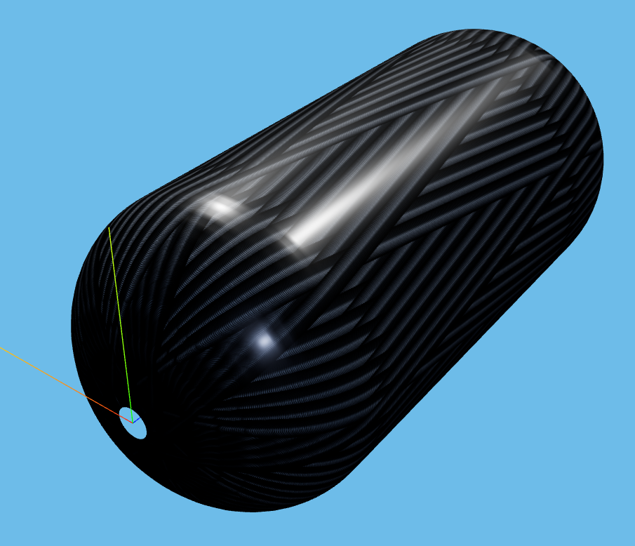
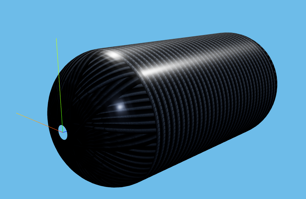
The way you walk, combined with how fast the box spins, decides where the ribbon ends up. Walk slowly while the box spins fast and the ribbon wraps almost like a band around the middle — that is a hoop wind, used in industry around 85–89° from the axis. Walk faster across the box while it spins and the ribbon goes diagonally — that is a helical wind, typically 15–55° in pressure vessels, 7–25° in COPVs and rocket cases. Barely walk at all and let the ribbon spiral toward the small openings at each end — that is a polar wind, used mainly to reinforce the dome region.
Every filament-wound part is some combination of those three motions, stacked into layers.
What is actually happening in the cell
In a real winding cell, four things are happening simultaneously:
- The fibre is being fed. The creel holds spools of dry tow or towpreg; pressure-vessel work commonly uses aerospace or industrial carbon tows selected for the design allowables. Each tow is pulled through a tensioner, with the setpoint chosen from tow size, resin system, machine architecture and process qualification. In wet winding the tow then passes through a resin bath; in towpreg winding the resin is already on the fibre.
- The mandrel is rotating. The mandrel is the male tool — its outer surface is the inner surface of the finished part. On a Type IV tank the mandrel is the polymer liner itself; on a Type III it is a thin metal liner; on a removable-mandrel job it is a sand, plaster, or segmented metal core that gets washed or unbolted out after cure. Mandrel rotation is usually continuous through a layer, with axis motion coordinated against carriage motion.
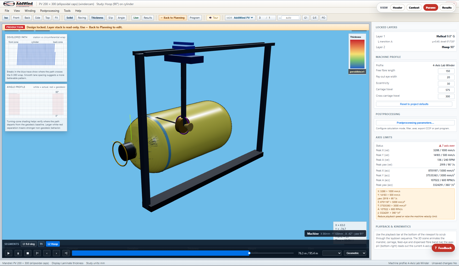
- The carriage is traversing. The carriage runs parallel to the mandrel axis, carrying the payout eye — the nozzle the fibre exits from. The synchronised motion of mandrel rotation and carriage translation decides exactly where every turn of fibre lands. On 4-axis and 6-axis machines the eye can also rotate and translate radially, which is what lets the fibre lay down cleanly on dome surfaces.
- A planner computed all of this in advance. Before the machine ran a single revolution, somebody (or some software) decided the winding angle, the number of circuits per pattern, the skip pattern, the band width, the dwell positions, and the layer order. That is what filament-winding planning software exists to do.
Continuous fibre placement is one of the defining features. Within a layer the fibre is one strand under tension from spool to mandrel; between layers, production planners often use short transition moves so the lay-up can continue without unwinding. Commercial tools may model these transitions explicitly, but their exact implementation depends on the machine and software workflow. This continuity is what gives filament-wound shells their characteristic strength — there are very few of the cut ends that limit chopped, woven, or short-fibre reinforcements in primary load paths.
What engineers often miss
Three things consistently catch teams new to filament winding off-guard.
The fibre cannot go everywhere. A geodesic — the "as-straight-as-possible" line on a curved surface — is the only path a dry fibre wants to follow without slipping. The Clairaut relation, r · sin α = C, says that for a given winding angle α on the cylinder the fibre cannot wrap closer to the axis than r = C on the dome. On a 200 mm cylinder wound at 15°, that minimum radius is about 26 mm; if the boss opening is 20 mm in radius, the fibre would have to wrap inside a hole that does not exist. Try it in AddWind and the status flips to CANNOT BE WOUND; the dome path visibly kinks at the boss circle. The winding angle article walks through the math.
The pattern has to close. A wind that does not close on itself leaves visible gaps or builds up thickness in the wrong places. Planners choose a number of circuits N and a skip number S so that, after enough cycles, the fibres uniformly tile the surface. This is the N/S or cycles you see in any winding planner. The pattern closure article walks through it.
The tape has finite width and thickness. Idealised path planners treat the fibre as a line. A real band is a few millimetres wide and a fraction of a millimetre thick. Adjacent bands can leave gaps or overlap. Because the band angle swings toward 90? near the boss, many overlapping bands per unit circumference means many overlapping layers per unit thickness, which is why dome ends of closed vessels are usually thicker than the cylinder. The exact ratio is a design outcome, not a universal constant. The tape width article covers the geometry.
How AddWind helps you see this
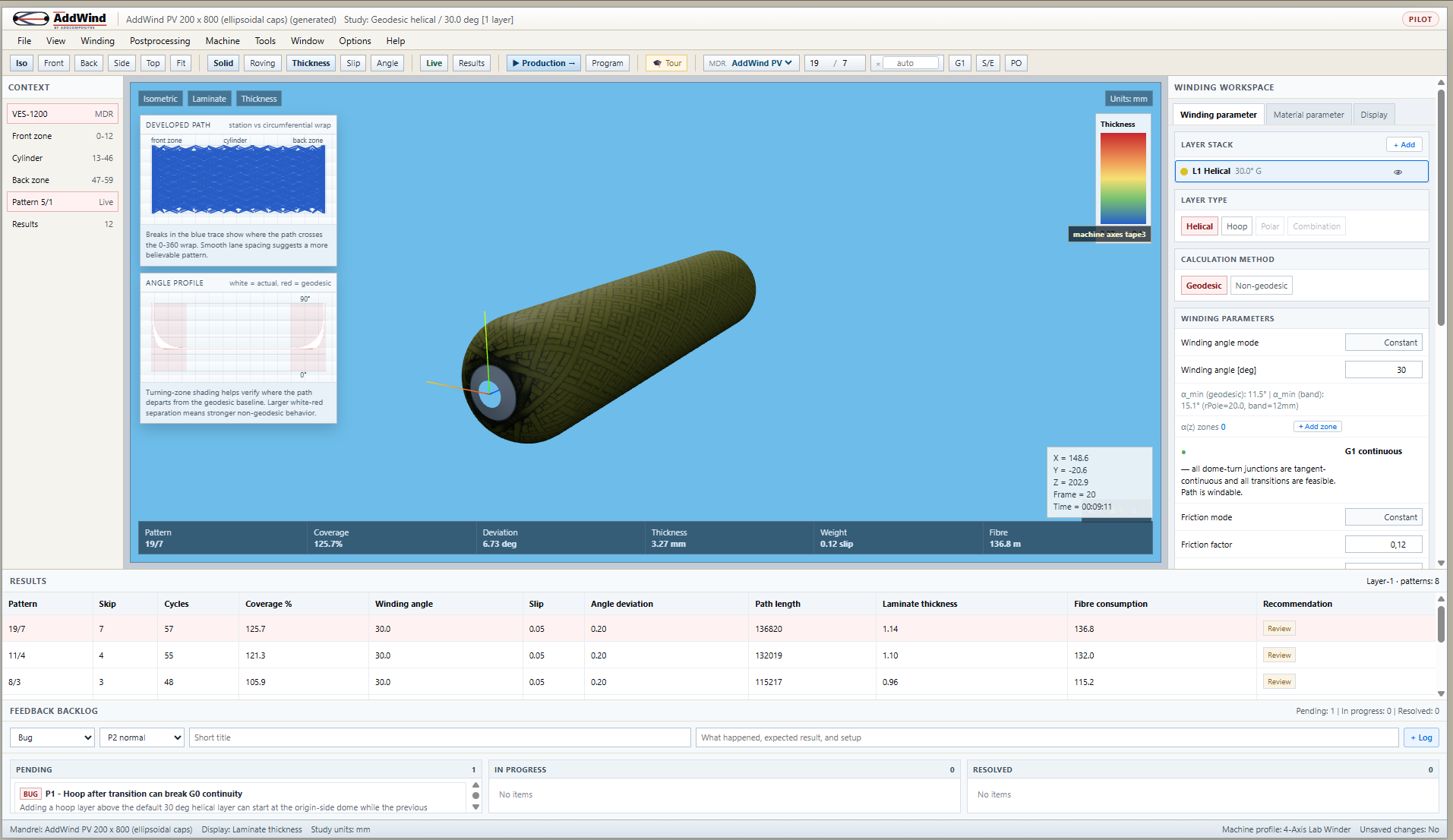
AddWind is a browser-based filament-winding planner that draws the fibre path as you move the sliders. You don't install anything; you don't load a CAD package; you pick a mandrel from a dropdown, choose a layer type, and watch the path appear.
For a first read of the process, three things are worth doing in the app:
- Open the simulator. The default mandrel — labelled LongTank in the project dropdown — is a representative pressure-vessel geometry (R ≈ 101 mm, ellipsoidal dome, 20 mm boss radius). The numbers in this article and the winding modes guide all use this mandrel.
- Switch the layer type between Hoop and Helical. Each one redraws interactively so you can build an intuition for what each layer family looks like. (Polar is a planned mode in the current build — you will see it greyed out in the layer-type panel.)
- Click the Iso → Front → Side → Top view buttons to walk around the part. The front view is the dome view — that is where almost every windability question lives.
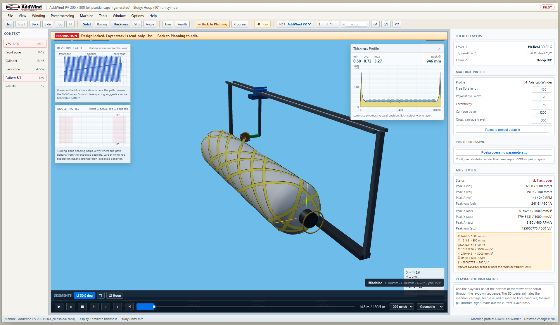
When you are ready to look under the hood, switch to the ? Production ? stage in the toolbar. The viewport drops in a representative carriage and payout eye, and the Program button opens a Motion Analysis chart with time-aligned traces for mandrel angle, carriage X, cross-feed Y and payout-eye yaw ? the same categories of motion a machine integration normally has to inspect before controller-specific export.
Practical takeaway
Filament winding is a continuous-fibre, path-controlled process. Three things drive the design — what fibre at what angle, how the pattern closes, and how the finite-width tape stacks up. If you can read those three things off a planner, you can read a winding job.
If you have never done that on a real planner, the fastest way is to open AddWind and try it, in this order:
- Pick the default LongTank mandrel.
- Switch between Hoop and Helical layer types and watch the path redraw.
- Sweep the winding angle on a helical layer from 25° down to 12°. Watch the dome status flip from green ("G1 continuous — Path is windable") to red ("CANNOT BE WOUND") as the geodesic stops fitting over the 20 mm boss.
- Toggle the Layer Stack on and add a second layer at a different angle. See how the dome covers up.
You will have a working mental model of filament winding in less time than it takes to read a textbook chapter.
Next step
Read The Filament Winding Machine, Explained for what every axis on the winder does, and how carriage and mandrel motions combine to produce a winding path. Or jump ahead to Hoop, Helical and Polar — The Three Winding Patterns for a deeper look at each pattern family.
To walk through a laminate yourself in the simulator:
Open AddWind → https://addwind.addcomposites.com/learn
About AddWind
AddWind is a browser-based filament-winding planner from AddComposites. It runs in the browser with no install, lets you draw and inspect a winding path against a parametric mandrel, and is the educational front end for the team's broader filament-winding tooling. The numbers and screenshots in this article were generated in the public AddWind build.
References
- Koussios, S. (2004). Filament Winding: a Unified Approach. Delft University Press. The standard textbook for geodesic and non-geodesic winding theory.
- Peters, S. T. (2011). Composite Filament Winding. ASM International. Process and equipment overview.
- Azeem, M., et al. (2022). Application of Filament Winding Technology in Composite Pressure Vessels and Challenges — A Review.
- AddComposites primer: https://www.addcomposites.com/post/filament-winding
- AddWind winding modes guide (this repo):
docs/winding-modes-guide.md.
Open AddWind, adjust the winding setup, and inspect the path, laminate and production motion in the same browser workspace.