Why the Winding Angle Matters in Filament Winding
The winding angle — the angle between the fibre and the mandrel axis — is the single number that controls almost every property of a wound layer. It decides the structural performance, the dome coverage, the pattern closure, the lay-down quality, and whether the layer can even be wound at all. A 3° change is enough to move a layer from "easy" to "physically impossible".
This article shows you why, with the maths in plain language and a live simulator you can poke at.
Why this matters
Two parts wound on the same mandrel with the same fibre and the same tension will have totally different strength, weight and failure behaviour if their winding angles differ by 10°. That is not a process imperfection — it is a direct consequence of the way fibres carry load. An angle that is wrong for the design can underperform structurally. An angle that is wrong for the geometry may not be windable at all.
So before you optimise anything else, you have to pick the angle. And before you pick the angle, you have to understand the two hard constraints it is squeezed between: structural demand from above, and windability from below.
The simple explanation
Imagine a balloon. Inflate it. Now imagine the rubber is made of fibres. The fibres going around the balloon (hoop direction) feel twice as much stress as the fibres going along the balloon (axial direction). That ratio — 2:1 — is true for any thin-wall cylinder under internal pressure.
If you arrange your fibres at angle α from the axis, each fibre carries roughly cos²α of axial load and sin²α of hoop load. To match the 2:1 stress ratio, you want tan²α = 2, which gives α ≈ 54.7°. That's the famous isotensoid angle. It is the angle at which the stress in every fibre is equalised, assuming the only load is internal pressure.
In practice, vessels are not only loaded by pressure — they have dome shapes, boss reinforcements, external loads, cyclic fatigue — and the optimum drifts. Most real composite pressure vessels use a mix of hoop layers (≈ 89°) and helical layers in the 20°–55° range.
What happens in the real process — Clairaut's relation
The second constraint is geometric. On a surface of revolution (like a pressure vessel mandrel), a geodesic — the "as-straight-as-possible" path the fibre wants to follow when it is dry — obeys Clairaut's relation:
> r · sin α = C
r is the local radius of the mandrel at any point along the fibre path. α is the winding angle at that point. C is a constant for that particular geodesic.
The consequence is: as the fibre travels from the cylinder onto the dome, the radius decreases, so the angle has to increase. At r = C, the angle hits 90° and the fibre cannot go any closer to the axis. C is the minimum radius the fibre can reach on a geodesic.
For a cylinder of radius R and a chosen cylinder-section angle α₀, that gives:
> C = R · sin α₀
If your boss has radius b, the geodesic can reach it only if C ≤ b. Otherwise the fibre wants to fall inside the boss circle, which physically means it slips off the dome edge.
Worked example — LongTank mandrel (R = 101 mm, boss radius = 20 mm)
| Cylinder angle α₀ | C = R · sin α₀ | Fits over 20 mm boss? |
|---|---|---|
| 25° | 42.7 mm | Yes, with margin |
| 18° | 31.2 mm | Yes, tight |
| 15° | 26.2 mm | Marginal — band edge encroaches |
| 12° | 21.0 mm | At the boss edge |
| 10° | 17.5 mm | No — inside the boss |
That table is a simplified way to build intuition for what AddWind visualizes as you move the angle slider: lower angles reach further toward the boss, while infeasible settings eventually produce a visible windability warning.
What engineers often miss
The cylinder angle is not the layer angle. The angle you set in your planner is the cylinder-section angle. The angle on the dome continuously increases as the fibre approaches the boss. By the time the fibre is wrapping the boss, the angle is essentially 90°. Always check the angle profile, not just the cylinder number.
Friction buys you a few degrees, not many. Non-geodesic winding lets the fibre deviate from the natural geodesic by an amount supported by friction between fibre and mandrel. The effective Clairaut constant shrinks roughly as C_eff = C_geo · (1 - k μ). A realistic wet-winding μ of 0.12 only shrinks the wrap by about 6%. A μ of 0.4 — which is unrealistic for almost any real fibre-mandrel pair — shrinks it by 20%. Friction is a refinement, not a get-out-of-jail card.
The same angle is not feasible on every mandrel. A 15° wind that is impossible on a small-boss tank can be perfectly feasible on a tank with the same cylinder radius but a larger boss. The constraint is the ratio between cylinder radius and boss radius, not either number alone.
Pattern closure changes with angle. The same vessel at 25° might close beautifully with N=3 circuits per pattern, but at 27° need N=5 to close. We cover this in the pattern closure article.
How AddWind helps visualize or check this
AddWind makes the angle question a slider, which is the right interaction for a quantity this important. Three things to try:
- Open the simulator. Pick the LongTank mandrel.
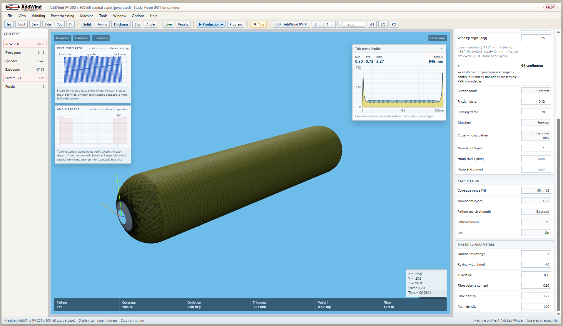
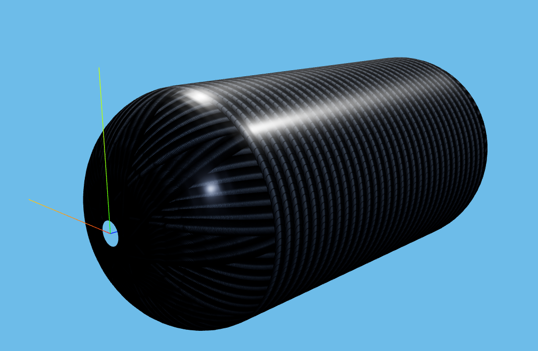
- Set Helical layer type, Geodesic calculation, angle = 25°. Click Iso then Front. Status reads green.
- Slowly drop the angle to 20°, 18°, 15°, 12°. Watch the status box and watch the dome wrap. The fibre visibly snaps when you go past the feasible angle.
- Now switch Calculation Method → Non-geodesic and set friction μ = 0.5. The infeasible angles get slightly more feasible — the fibre wraps closer to the boss. Set μ back to 0.12 (a realistic wet-winding value) and notice how little it helps.
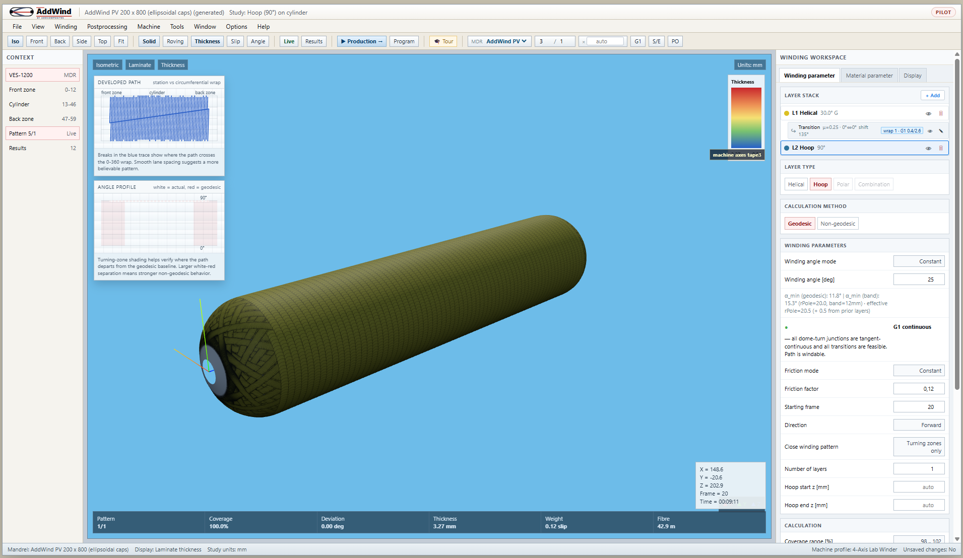
The angle-profile chart on the right (#angle-svg in the app) is your friend here. It shows the commanded path angle along the whole layer, with the geodesic baseline overlaid. Big gaps between the two mean the fibre is being asked to slip — which it may or may not actually do depending on friction.
Practical takeaway
When you pick a winding angle, do these three checks in order:
- Structural — does this angle carry the load split you need? For pure internal pressure, 54.7° is theoretical optimum; 25-30° helical + 89° hoop is the common practical recipe.
- Geometric — does
R · sin αfit comfortably inside your boss radius? Aim forC ≤ 0.7 · boss radiusso the band has clearance. - Pattern — at the chosen angle, does the layer close cleanly at a reasonable number of circuits?
If you can pass all three, you have a wound layer. If you cannot, the angle is the first thing to change.
Next step
A windable angle is necessary but not sufficient — the layer also has to cover the surface. Read Pattern Closure, Skip Cycles and Coverage to see how circuits, skip patterns and cycles fill in the cylinder.
Or open the simulator and sweep the angle: https://addwind.addcomposites.com.
References
- Koussios, S. (2004). Filament Winding: a Unified Approach, Chapter 4 (Geodesic winding) and Chapter 5 (Non-geodesic winding).
- Vasiliev, V. V., Krikanov, A. A., Razin, A. F. (2003). New generation of filament-wound composite pressure vessels for commercial applications.
- Hojjati, M., Hoa, S. V. (2018). Path calculation technology and opportunities in dry fiber winding — a review.
- AddWind internal:
docs/winding-modes-guide.md.
Open AddWind, adjust the winding setup, and inspect the path, laminate and production motion in the same browser workspace.