
Pattern Closure, Skip Cycles and Coverage in Filament Winding
Open any filament-winding planner and you will be asked for a number called N (or "circuits per pattern"), a number called S (or "skip"), and a number called cycles. They look like winding-software trivia. They are not. They decide whether your layer covers the cylinder uniformly or leaves visible bands and gaps.
This article explains what N, S and cycles actually mean, how they combine, and how to read pattern closure directly off the AddWind developed-path chart.
Why this matters
A filament-wound layer is built by laying fibre band after fibre band around the mandrel. After every circuit (one go around the mandrel and back), the band starts at a slightly different position. If those starting positions are chosen well, the bands tile the cylinder uniformly. If they are chosen badly, you get clumps of fibre in some places and bare mandrel in others. The pattern math is how you make the good choice deterministically.
If pattern closure is poor, post-processing cannot move already-laid fibre. The usual options are to change the pattern, change the layer setup, or accept a qualified nonuniformity only if the design allows it.
The simple explanation
Picture the cylinder unwrapped into a flat rectangle. The width of the rectangle is the cylinder circumference; the length is the cylinder length. A single circuit of helical winding shows up as one diagonal line across the rectangle. The next circuit lands as another diagonal line, parallel to the first, but starting at a slightly shifted position.
The shift is set by the winding mechanics — every full mandrel rotation while the carriage is traversing produces a band that is offset from the previous one. To cover the cylinder uniformly, you want those offsets to add up to exactly one full circumference after some integer number of circuits, with no two bands landing in the same place.
That integer is N, the number of circuits per pattern. After N circuits, the pattern advances to the next "slot". After enough cycles, every slot is full.
S, the skip, controls which slot the next circuit lands in. S = 1 means the next band is placed in the slot immediately next to the previous one. S = 2 means it skips one slot. Different skips produce different visual patterns — and different temporal coverage profiles.
Cycles is how many times you repeat the N-circuit pattern. More cycles = more coverage, less visible gaps, more material laid down.
What happens in the real process
A skilled winding programmer thinks about pattern closure in three steps:
- Pick a winding angle and band width. These together set the natural circuit-to-circuit shift
Δθin degrees around the mandrel. - Compute N so that
N · Δθis close to a full 360°. The N that satisfies this is the closure number for the geometry. Commercial planners and AddWind-style tools can compute candidate closure choices for you, but the engineer still has to verify the result. - Pick S and cycles to control how the cylinder fills in temporally. A higher S spreads the coverage out evenly over the layer's lifetime; a lower S fills adjacent slots first.
There is one important subtlety. The closure number N depends on the cylinder and the dome geometry, because each circuit has to wrap a dome at each end. The dome wrap contributes extra fractional turns that the planner has to account for. That is why the same winding angle on two different mandrels can need different N values to close.
What engineers often miss
N is not a design knob — it is a result. Many beginners try to pick N freely. They cannot. For a given mandrel, fibre, winding angle and band width, there are only a handful of integer N values that produce closure. Picking a "creative" N value just means the pattern does not close.
S is the real design knob. Two different S values with the same N produce dramatically different temporal coverage. Low S tends to fill nearby slots earlier; higher S can distribute coverage more broadly over the layer. Which one you want depends on whether you care about coverage uniformity at intermediate cycle counts, or only at the final state.
Cycles trade material for coverage. More cycles means more fibre, more cost, more part weight. The minimum cycles for full coverage is whatever the band-width math says (typically 1–3 patterns). Anything beyond that is structural reinforcement.
The pattern table is your audit trail. AddWind shows a results table with the chosen N, S, cycles, closure-error percentage and coverage percentage. If the closure error is non-zero, the pattern is not closing — fix it before sending the program to the machine.
How AddWind helps visualize or check this
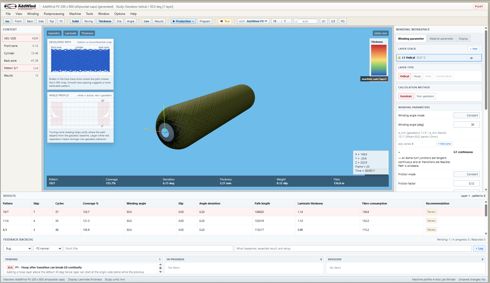
The developed-path chart in AddWind (#developed-svg in the app) is the right tool for this. It unwraps the cylinder into a flat strip and draws every fibre band as a diagonal line.
Three things to try:
- Open AddWind, pick a mandrel, set Helical layer type and angle = 25°.
- Open the N / S / cycles controls in the toolbar. Start with one of the suggested N/S/cycles combinations. Look at the developed chart and check whether the diagonal bands are evenly spaced.
- Change cycles to 3. Now you see nine lines. The pattern has filled in three slots; the cylinder is starting to look striped.
- Change S from 1 to 2. The order in which slots fill changes — same final coverage, different intermediate states.
- Try a different N value that closes poorly for the chosen setup. The developed chart shows the lines drifting; the coverage chart and pattern-results table show the closure error growing.
Practical takeaway
For a first wound layer, follow this recipe:
- Pick angle and band width based on structural and lay-down constraints (see articles 04 and 06).
- Let the planner suggest N, then verify it. Avoid overriding it unless you understand the closure tradeoff.
- Pick S based on the coverage order you want. Lower skips are easier to reason about; higher skips can distribute coverage more broadly before the layer is complete.
- Pick cycles by band-width math — typically
ceil(band_width / desired_layer_thickness)for the simplest case. Add 1 or 2 if you want margin. - Verify on the developed-path chart before you generate a program.
Next step
Pattern closure assumes the bands tile cleanly side by side. That assumption depends on the physical band — its width, its thickness, the gaps and overlaps between adjacent bands. Read Tape Width, Thickness, Gaps and Overlaps for the geometry behind the math.
Or open the simulator and toggle N and cycles yourself: https://addwind.addcomposites.com.
References
- Park, J., Lee, B. (2002). An expert system for filament winding pattern design, Composites A 33. The original N/S algorithm reference.
- Koussios, S. (2004). Filament Winding: a Unified Approach, Chapter 6 (Pattern design).
- CADWIND user manual — sections on Pattern numbers and Combination winding.
- AddWind internal:
docs/winding-modes-guide.md.
Open AddWind, adjust the winding setup, and inspect the path, laminate and production motion in the same browser workspace.