Tape Width, Thickness, Gaps and Overlaps in Filament Winding
Many first-pass path-planning models treat the fibre centerline as a line. The real fibre is a band, several millimetres wide and a tenth of a millimetre thick. Most laminate quality problems live in the difference between those two pictures.
This article walks through the geometry of the real band, explains where gaps and overlaps come from, and shows how to spot both in AddWind's Thickness mode before they show up on the part.
Why this matters
The thickness of a wound layer is not constant. It depends on how many band edges overlap at each point, which depends on the chosen pattern, angle, band width and mandrel geometry. Get this wrong and you can create two common failure modes:
- Gaps — places where adjacent bands do not touch. The mandrel shows through. Locally weak.
- Overlaps — places where adjacent bands stack on top of each other. Locally thick, locally over-built, and a source of pressure-side voids during cure.
On a dome, where the geometry forces bands to converge toward the boss, overlap is common and must be managed with angle, band width, pattern and stack sequence.
The simple explanation
A single tow is one continuous bundle of fibres straight off a spool. A band is a group of tows laid side-by-side through the same payout eye — typically 1, 2, 4 or 8 tows wide. The nominal band width w_band is set by tow count, tow spreading and any intended gap between tow ends.
When the carriage walks across the mandrel, the band lays down as a strip. The strip width (measured perpendicular to the fibre direction) is w_band. The strip width measured along the mandrel circumference (in the developed view) is wider than w_band because the fibre is at an angle: w_strip = w_band / cos(α). That 1/cos α factor is why a 15° wind covers far more circumferential distance per band than a 75° wind.
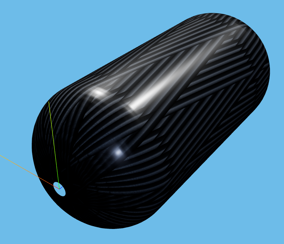
That same geometric effect helps explain why dome regions are often thicker than cylinder mid-span for closed-end vessels. As the fibre converges toward the boss, the local angle and available circumference change, so more bands compete for less surface area.
What happens in the real process
In real winding, three things complicate the simple geometry:
Spread. Tows are flexible. Under tension they can spread, and the actual band width on the mandrel may differ from the nominal tow-count estimate. Wet winding, towpreg, tow size and spreading hardware all change the result.
Tension nesting. When a fresh band lays over an existing band on the dome, it deforms the existing band slightly and "nests" between adjacent bands. Nesting reduces apparent thickness; ignoring it overestimates buildup.
Resin migration. In wet winding, resin moves under fibre tension during cure. Local fibre-volume fraction is higher at the bottom of overlaps and lower at the top. The overall thickness measured after cure can be significantly less than the lay-up thickness.
These are real-world corrections that planners apply on top of the geometric model. AddWind today uses a clean geometric visualization model for buildup. Treat the values as planning indicators, not as validated cured-laminate thickness predictions.
What engineers often miss
On a closed pressure vessel, the dome is commonly thicker than the cylinder. This follows from continuous-fibre wrapping over a boss and from the local reinforcement needs around the dome and boss interface. The exact ratio depends on design rules, boss geometry, material, pattern and process qualification.
Pattern choice changes thickness distribution. A pattern with S = 1 (fill adjacent slots first) creates locally thick stripes early in the lay-up that persist through cure. A pattern with S = 2 or higher distributes the buildup more evenly. Look at the thickness mode at intermediate cycle counts, not just final.
Band width interacts with angle. A small band on a high-angle wind covers very little circumference per circuit, so you need many circuits to close the pattern — and many circuits means high local thickness in the slots where they all converge. A wide band on a low-angle wind covers a lot of circumference per circuit, closes the pattern fast, and stays thin.
Gaps are sometimes intentional. Some early hoop layers are deliberately wound with small gaps to let later layers nest into them, reducing total buildup. This is a design decision, not a defect. Read the layer stack carefully.
How AddWind helps visualize or check this
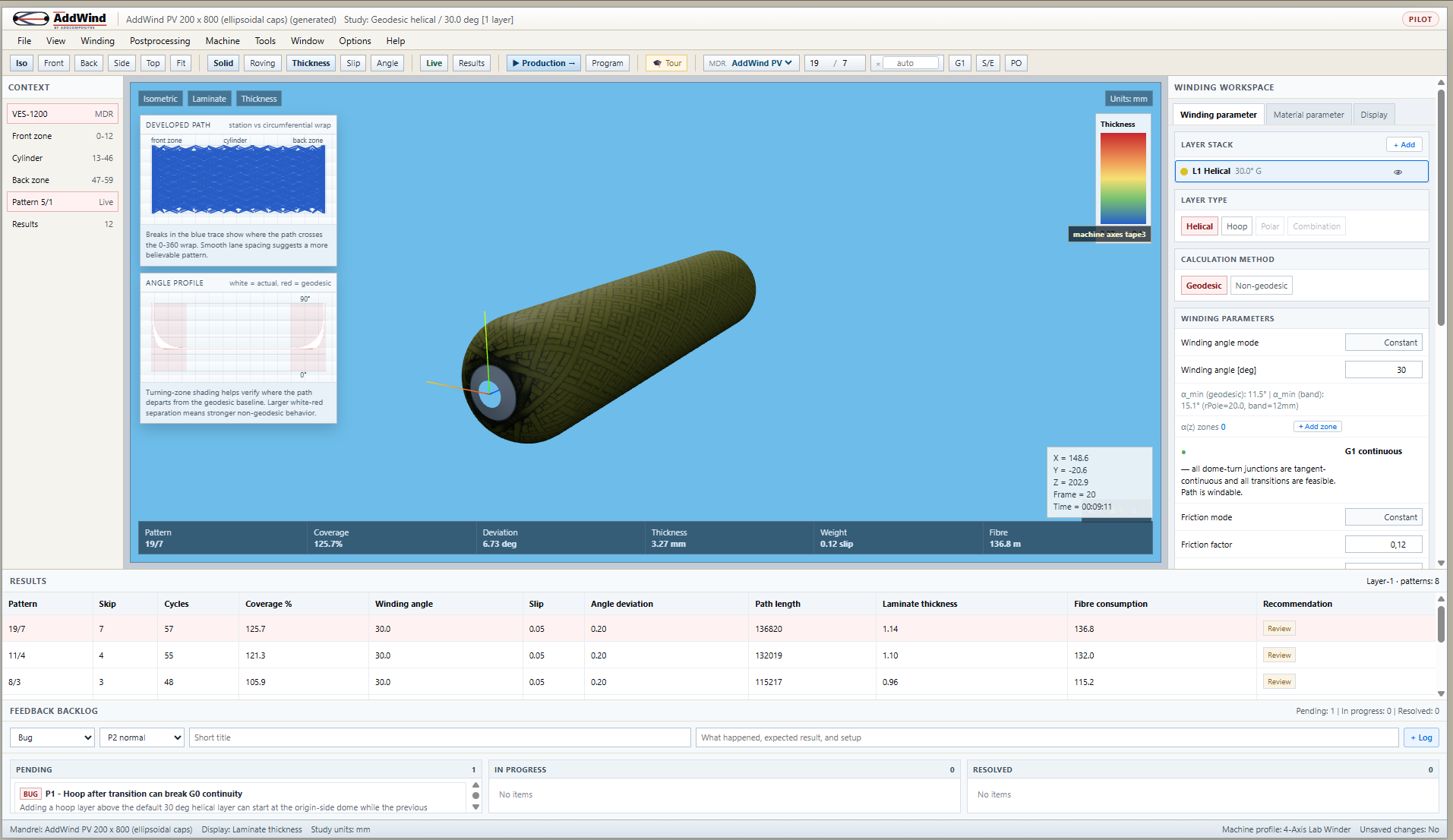
Switch the viewport mode toolbar from Roving to Thickness. The fibre disappears and is replaced by a colour-coded thickness map. Red means locally thicker; blue means locally thinner. The legend on the right shows the min/max values in millimetres.
Three things to try:
- Open AddWind, pick a mandrel. Wind a single 25° helical layer. Switch to Thickness mode.
- Look at the dome. The buildup near the boss is dramatic. That is the polar buildup we cover in article 07.
- Add a second helical layer at 55°. The thickness map now shows where the two layers overlap most and least.
- Switch back to Roving mode and use Slip view (the toolbar toggle) to colour each band by angle deviation from the geodesic. Patches of high deviation are where the band is being asked to move sideways — usually exactly where the buildup is highest.
Practical takeaway
When you design a layer, ask the band geometry three questions:
- How wide is the band on the mandrel at the cylinder angle? If
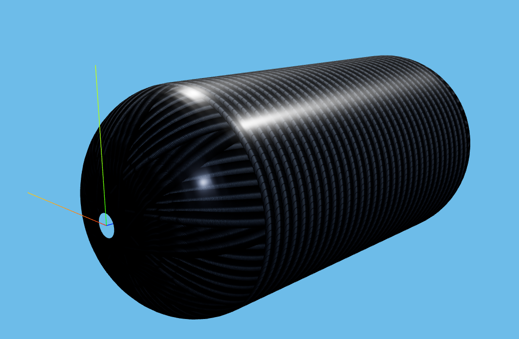
w_bandis comparable to the cylinder length, you only need one or two circuits to cover; if it is small, you need many. - How does it converge on the dome? Look at AddWind's Thickness mode at the boss. If the buildup is much higher than the cylinder mid-span, consider reducing band width, changing angle, changing pattern, or revisiting the dome/boss design.
- Where are the overlaps in the developed view? They are candidate quality-risk regions. Make sure the next layer up does not have its overlaps in the same places — stagger them.
Next step
The biggest single source of thickness variation is what happens at the dome. Read Dome Turnarounds and Polar Buildup for the geometry and the strategies.
Or open the simulator and switch on Thickness mode: https://addwind.addcomposites.com.
References
- Koussios, S. (2004). Filament Winding: a Unified Approach, Chapter 7 (Band geometry).
- Mertiny, P., Ellyin, F. (2002). Influence of the filament winding tension on physical and mechanical properties of reinforced composites.
- Sorrentino, L., et al. (2019). Robotic filament winding: an innovative technology to manufacture complex shape structural parts.
- AddWind internal:
docs/winding-modes-guide.md.
Open AddWind, adjust the winding setup, and inspect the path, laminate and production motion in the same browser workspace.