Hoop, Helical and Polar Winding Patterns Explained
There are three commonly discussed families of winding paths. Real pressure-vessel laminates usually combine hoop and helical layers, and may add low-angle or polar-style reinforcement near the dome and boss when the design needs it. This article walks through each one, what it physically carries, and how to read it off a planner.
Why this matters
A composite pressure vessel sees two structural loads:
- Hoop stress — circumferential load from internal pressure, exactly twice the axial stress for a thin-wall cylinder. Carried by fibres aligned around the cylinder.
- Axial stress — load along the cylinder axis from internal pressure. Carried by fibres aligned along the cylinder.
A single layer of fibres can only carry load in roughly its own direction. So you need at least two families of layers — and on a vessel with closed ends (which is every pressure vessel), you also need a layer that wraps over the dome ends.
That is the mechanical reason these path families exist, even though the exact stack depends on vessel geometry, boss design, material system and qualification history.
The three families
Hoop winding — 88° to 90°
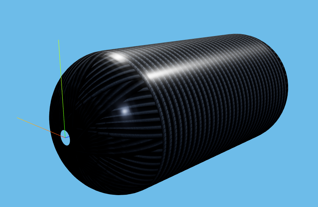
A hoop winding is essentially a band wrapping around the cylinder. The winding angle is close to 90° — close to perpendicular to the mandrel axis — so each turn of fibre is nearly a circle.
- What it carries: hoop stress (the dominant load in a pressure vessel).
- Where it goes: cylinder section only. A hoop layer does not cover the domes; if you tried, the fibre would have nothing to anchor against and would slip off.
- Pattern: simple. Adjacent bands sit side by side along the cylinder length. Pattern closure is trivial.
- Common typical use: the outermost or innermost layer of a composite pressure vessel, or both.
Helical winding — 5° to 88°
A helical winding crosses the cylinder at an angle. Two crossing layers (one at +α, one at −α) cover the surface in a diamond pattern.
- What it carries: a combination of hoop and axial stress, with the split set by the winding angle. A 54.7° "isotensoid" angle is the theoretical optimum for a thin-wall cylinder under pressure, because at that angle the hoop-to-axial stiffness ratio matches the hoop-to-axial stress ratio. In practice optimum angles drift between 25° and 60° depending on dome shape, boss size and external loads.
- Where it goes: cylinder and dome. The same continuous path goes from one dome, across the cylinder, around the far dome, and back. That is the defining feature of a helical layer.
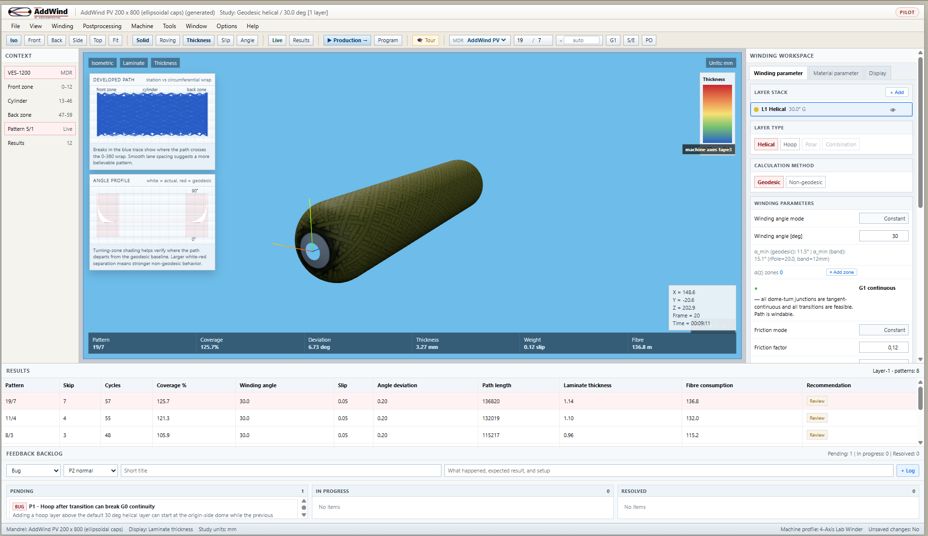
- Pattern: non-trivial. The fibre crosses itself over many circuits, and the pattern only "closes" — covers the cylinder uniformly — at specific combinations of circuits per pattern and skip count. AddWind shows the closure live.
- Common typical use: the structural backbone of almost every composite pressure vessel.
Polar winding — low angle, dome-to-dome
A polar winding has a very low angle (typically below 15°) and passes near or over the poles of both domes. Instead of crossing the cylinder at an angle, it almost runs axially.
- What it carries: dome bridging and axial load.
- Where it goes: primarily the domes. On the cylinder, polar layers run almost axially.
- Pattern: the path passes near the pole on one dome, wraps tightly around the boss, returns along the opposite side, and wraps the other dome's boss. When polar-style reinforcement is used, it is often placed early in the stack so it sits close to the liner and boss geometry, but sequencing is a design and process decision.
- Common typical use: dome reinforcement on Type IV pressure vessels, polar boss buildup.
What happens in the real process
A simplified Type-IV hydrogen-tank laminate might look like this, but the actual qualified sequence is design-specific:
``` Boss / liner ↓
- Polar layer (axial reinforcement, sits against liner)
- Helical 25° layer (general structural backbone)
- Helical 25° layer (opposite hand, closes the pattern)
- Hoop layer (cylinder hoop strength)
- Helical 55° layer (extra hoop+axial coupling)
- Hoop layer (final outer hoop wrap)
↓ Cure / surface ```
Production planners often try to keep the stack continuous, using dwell and transition moves where the machine and process require them. AddWind currently visualizes the geometric layer stack and records transition intent, but full layer-to-layer transition visualization and export are still on the roadmap (Phase 3B.3 in docs/design/14-layer-transitions-plan.md).
What engineers often miss
Hoop is hard to replace. Some early designs try to skip dedicated hoop layers and use very-high-angle helical layers (e.g. 85?) instead. They look similar in CAD, but they behave differently in cure and pressure cycling because a high-angle helical still has axial components and a dome turnaround.
Polar-style layers are sequence-sensitive. On Type IV vessels, low-angle or polar-style reinforcement is often placed near the liner because it has a small contact patch on the cylinder. Putting it later can change its effective angle because it sits over an already-thicker laminate.
The angle on the cylinder is not the angle on the dome. A helical layer wound at 25° on the cylinder has a continuously changing angle on the dome — the same fibre is at 25° on the cylinder, ~45° halfway down the dome, and ~90° at the boss. Always look at the angle profile chart, not just the cylinder angle, when judging a laminate.
How AddWind helps visualize or check this
AddWind currently exposes Hoop and Helical layer workflows. Dedicated Polar mode is still a roadmap item, so the practical way to study polar-like behavior today is a low-angle helical layer with the windability warnings visible.
The fastest way to build intuition is:
- Open the simulator at https://addwind.addcomposites.com.
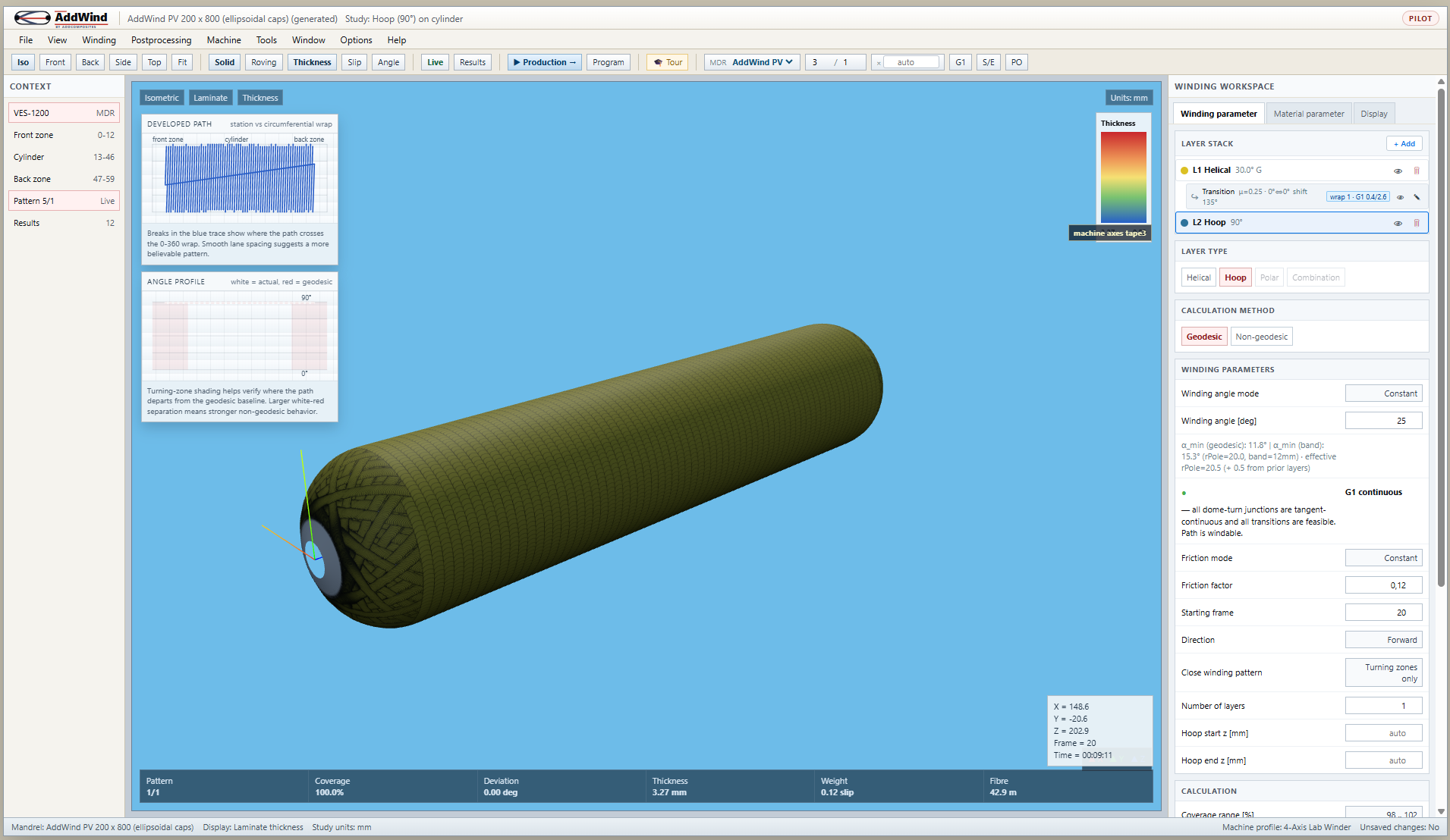
- Set Layer Type → Hoop. Look at the layer stack and the cylinder coverage.
- Switch to Layer Type → Helical, angle = 25°. Watch the dome wrap fill in.
- Drop the angle to 15° and then 12°. Notice the status warning appear, then the CANNOT BE WOUND flag.
- Open the Layer Stack panel and add layers in the order shown above. The right-hand panel shows you the developed-path chart for the whole laminate.
The developed-path chart is especially useful here: it unwraps the surface into a flat strip and shows coverage as a stripe pattern. Layers that close cleanly show even stripes; layers that do not close show clumping.
Practical takeaway
For a first conceptual pass at a vessel laminate, a common starting point is:
- 2 hoop layers for circumferential strength.
- 2-4 helical layers at 25-30° for axial strength and dome coverage.
- Low-angle/polar-style reinforcement if boss or dome reinforcement is marginal.
Tune from there with FEA, manufacturing trials and qualified design rules. The point of starting with a windable conceptual stack is that a structurally attractive but un-windable laminate has no manufacturing value.
Next step
The single most important number in any layer is the winding angle. Read Why the Winding Angle Matters to see why a 3° change can move a part from "easy to wind" to "physically impossible".
Or open the simulator and compare Hoop, Helical and low-angle helical behavior: https://addwind.addcomposites.com.
References
- Koussios, S. (2004). Filament Winding: a Unified Approach, Chapters 4–6.
- Park, J., Lee, B. (2002). An expert system for filament winding pattern design, Composites A 33. Origin of the N/S pattern algorithm.
- CADWIND user manual — sections on Helical and Combination winding.
- AddComposites primer: https://www.addcomposites.com/post/filament-winding
Open AddWind, adjust the winding setup, and inspect the path, laminate and production motion in the same browser workspace.