
The Filament Winding Machine, Explained Axis by Axis
A filament winding machine is mechanically deceptive: the visible motion can look simple, but the process quality depends on how accurately several axes coordinate. A spindle spins the mandrel. A carriage moves parallel to the mandrel axis. A payout eye guides the fibre onto the part. The remaining machine details define the part envelope, lay-down quality and production speed. The interesting question is which details your part actually needs.
This article walks through the axes you find on real winders — 2-axis, 4-axis, 6-axis robotic — and shows what each one buys you. It also shows how to read those motions off a planner, using AddWind's Production view as the live example.
Why this matters
The number of axes on your winder decides what shapes you can wind, how cleanly the fibre is laid down, and how much hand-tuning you will do per part. Two-axis machines are cheap and reliable but are generally limited to axisymmetric, near-cylindrical parts. Additional axes (typically 4+) give the payout eye the orientation control needed for dome turnarounds on closed vessels. Six-axis robotic cells extend the envelope further to shapes that were difficult to wind a generation ago — pipe T-junctions, automotive structural parts, certain non-cylindrical sections.
Spec the wrong number of axes and you either pay too much for a robot you will not use, or you commit to a machine that cannot make the parts you sold.
The simple explanation
Every filament winder has a rotating axis (the mandrel) and a translating axis (the carriage). The minimum useful winder has exactly those two. From there, every additional axis adds a degree of freedom to the payout eye relative to the mandrel surface.
Here is one common way to describe the machine axes:
| Axis | What it does | Why you'd want it |
|---|---|---|
| A — mandrel rotation | Spins the part. The rotation angle synchronised with carriage position decides where the fibre lands. | Every winder has this. |
| X — carriage translation | Walks the carriage along the mandrel axis. | Every winder has this. |
| Y — radial / cross-feed | Moves the payout eye in and out, controlling stand-off distance from the surface. | Needed to keep stand-off constant across domes, where mandrel radius changes. |
| B — payout-eye rotation | Rotates the eye around the carriage so the eye can tilt to match the fibre direction. | Needed for clean lay-down at low and high winding angles. |
| C — second rotation / tilt | Adds an extra rotational degree at the eye. | Needed for complex non-axisymmetric parts. |
| Robot wrist (6-axis) | Replaces the carriage with a robot arm, giving the eye full 6-DOF reach. | Needed for tee fittings, branching structures, non-cylindrical parts. |
What happens in the real process
When a winding job starts, the controller typically follows a synchronised motion program: mandrel rotation, carriage position, cross-feed position and payout-eye orientation are coordinated over time. That program came from a planner or post-processor, but the machine is not just a passive playback device; it is constrained by axis limits, acceleration, tension control, safety interlocks and operator setup.
What the operator actually controls in real time is small but important:
- Fibre tension. Too low and the wrap is loose and slips. Too high and the fibre cuts itself, the mandrel deflects, or the resin gets squeezed out of the band.
- Bath conditions (wet winding). Resin viscosity, bath level, scraper position. These decide fibre-volume fraction and surface tack.
- Mandrel surface preparation. Release agent, peel ply, foil, or PVA — each gives a different fibre-mandrel friction coefficient, which determines what non-geodesic paths are stable.
- Dwells. A dwell is a mandrel rotation with the carriage stopped or nearly stopped, used to anchor the fibre at a turning point. Commercial winding planners commonly expose dwell-like parameters, but the exact implementation is machine- and workflow-specific.
What engineers often miss
The payout eye is not the contact point. The fibre leaves the eye at one point and lands on the mandrel at a different point. The straight-line segment between them is called the free length or payout length. Its direction tells you the winding angle at the touchdown point. If your machine cannot tilt the eye, low-angle and high-angle layers can leave the eye with a mismatch between eye orientation and touchdown direction. That mismatch is one common source of lay-down quality issues.
More axes is not always better. A 6-axis robot cell is a powerful tool, but many axisymmetric pressure vessels are still better served by a well-tuned dedicated 4-axis winder. The robot becomes attractive when the part is not axisymmetric or when the process needs reach that a carriage machine cannot provide.
The mandrel is part of the machine. A flexible mandrel, a mandrel that runs out, or a mandrel that thermally expands during cure will all destroy windability. Treat mandrel design with the same care as tooling design for any other process.
How AddWind helps visualize or check this
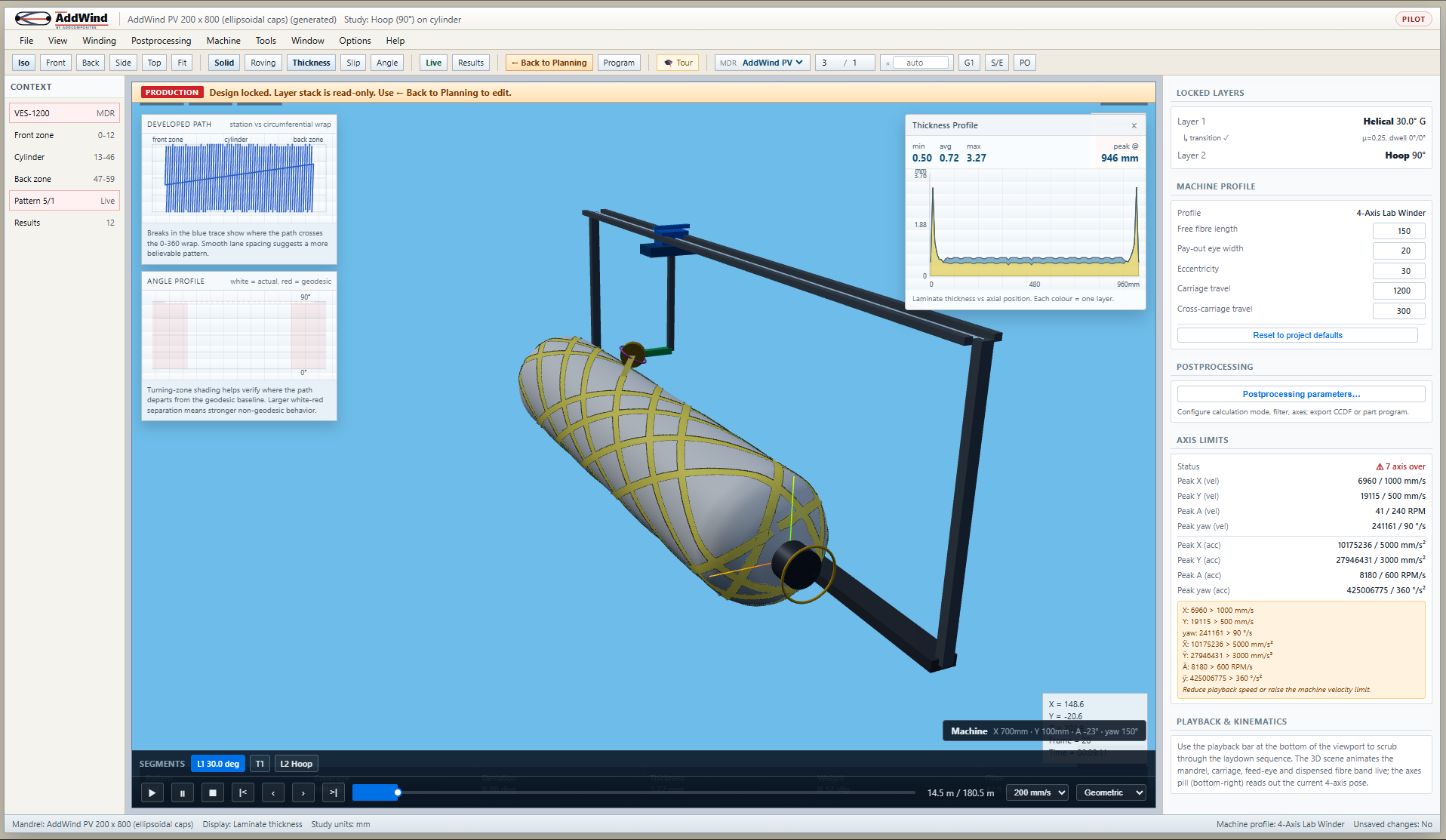
AddWind has two stages — Planning and Production. Planning is where you design the layer stack. Production is where the machine motion comes alive.
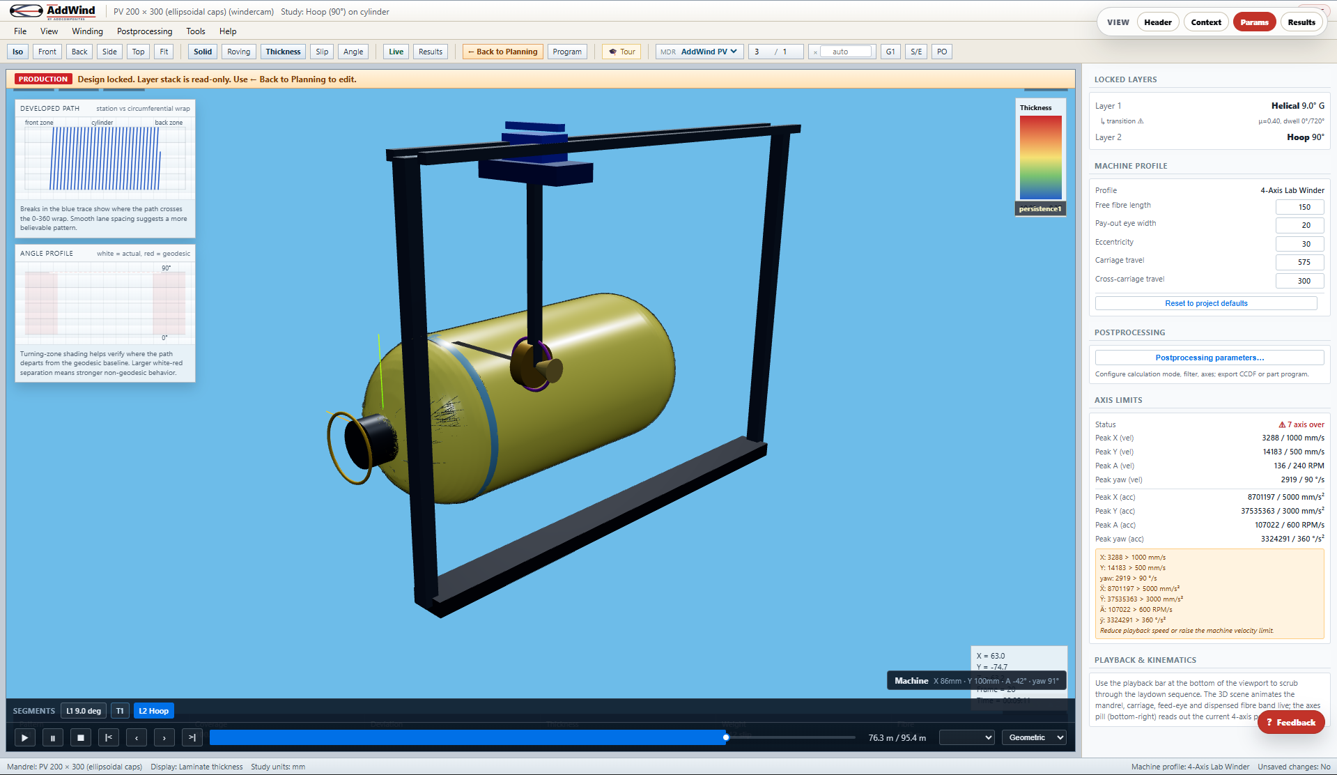
Click the ▶ Production → button in the toolbar. The viewport switches: now you see the carriage, the payout eye, and the mandrel rotating together. Open the Program chart and you get a synchronised plot of mandrel angle, carriage position, and free-length angle — the same time-aligned data the real machine would receive.
Three things are worth trying in the Production view:
- Watch the payout eye as the wind crosses a dome. The free length swings from near-vertical to near-horizontal — that swing is the kind of orientation change a real payout axis may need to handle.
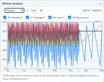
- Open the Motion Analysis chart (the Program toolbar button). Look at the carriage-velocity trace. The peak velocity is what your machine's linear axis has to handle without skipping steps.
- Zoom in on the tangent payout in the viewport. You can see the band exiting the eye and contacting the mandrel. That contact geometry is what decides lay-down quality.
Practical takeaway
When you read a machine spec or a quote, look for three numbers in this order:
- Number of controllable axes ? often 2, 4, or 6+. This strongly influences your shape envelope.
- Maximum carriage velocity and mandrel rpm — these multiply into your throughput at any given angle.
- Tension-control method and number of tow ends — these decide your laminate quality and your maximum band width.
Drive type, fieldbus and HMI still matter, but only after the machine can satisfy the part envelope, throughput envelope and tension-control needs.
Next step
Now that you know what the machine does, the next question is what to ask of it. Read Hoop, Helical and Polar Winding Patterns to see the three families of layers you can wind, and when to pick which.
Or open the simulator's Production view and click through a few mandrels: https://addwind.addcomposites.com.
References
- Peters, S. T. (2011). Composite Filament Winding, Chapter 2 (machine architectures). ASM International.
- Quanjin, M., et al. (2018). Filament winding applications, in Reference Module in Materials Science and Materials Engineering.
- Sorrentino, L., et al. (2019). Robotic filament winding: an innovative technology to manufacture complex shape structural parts.
- CADWIND user manual (machine kinematics section).
Open AddWind, adjust the winding setup, and inspect the path, laminate and production motion in the same browser workspace.