Dome Turnarounds and Polar Buildup in Filament Winding
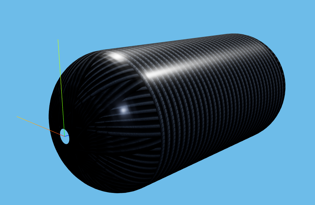
The dome is where every filament-winding design either works or quietly fails. The fibres come off the cylinder, converge toward a small boss, wrap that boss, and head back. The geometry forces them to pile up. The buildup is unavoidable. The skill is in controlling it.
This article walks through the geometry of the turnaround, the role of dwells, and the strategies designers use to keep the polar region structurally clean.
Why this matters
Pressure-vessel dome and boss regions are frequent design-critical areas, alongside the cylinder-to-dome transition. These regions deserve separate checks because curvature, boss hardware and local laminate buildup all interact there.
Dome winding choices strongly influence both regions, but they are not the only drivers; boss design, liner behavior, material allowables, cure and test conditions also matter.
The simple explanation
As the fibre travels from the cylinder onto the dome, three things happen at once:
- The local radius shrinks. A fibre wound at 25° on the cylinder is at ~45° at mid-dome and approaches 90° at the boss. The angle is forced up by Clairaut's relation (see article 04).
- The band's circumferential coverage collapses. Per article 06, circumferential coverage is
w_band / cos α. As α approaches 90°,cos αapproaches zero, and circumferential coverage collapses. That is the geometric reason for polar buildup. - Every band converges toward the boss. Many band edges per unit circumference means many overlap stacks per unit thickness. The local laminate thickness grows roughly as
t_cylinder / cos αfor a single layer.
The result is a dome thickness profile that can rise strongly near the boss. The exact local ratio depends on the layer stack, band width, boss geometry and compaction model.
What happens in the real process
In a real winding cell, the dome turnaround involves more than just geometry:
The fibre has to find tension equilibrium. As the fibre wraps the boss, the tension is supported by friction on the dome surface and by the boss edge geometry itself. Boss edge geometry affects anchoring and slip, but sharp edges also create damage and stress-concentration risks, so the boss relief must be designed for both manufacturability and structural performance.
A dwell is often used at the turnaround. A dwell is one full mandrel rotation (typically 360°) with the carriage stopped at one position. It wraps the fibre tightly at a single z-position before the next motion begins. Commercial winding tools often expose dwell or turnaround parameters. AddWind records dwell/transition intent in the current planning workflow, while complete production-grade transition handling is still being developed.
The dome can be reinforced separately. Many pressure vessels add low-angle or polar-style reinforcement near the dome and boss. These layers may contribute less to cylinder hoop strength but can be important for dome capacity.
The boss itself is a structural element. Metal bosses are designed to engage the fibre wrap. The geometry of the relief groove on the boss, the boss-to-liner sealing surface, and the boss flange diameter all interact with the winding pattern.
What engineers often miss
The dome thickness is not a process error to be eliminated. It is a structural feature. The polar region needs to carry the meridional and circumferential stresses around the boss. Cylinder reinforcement does not help here.
Dwells are not free. A dwell anchors the fibre but also adds a local thick ring where every turn of the dwell lands. Excessive dwells produce visible bumps on the cured vessel and stress concentrations under it.
The choice of dome shape matters as much as the winding. A geodesic isotensoid dome — designed so the fibre under pressure has uniform stress everywhere — is the lowest-mass solution. A spherical dome is easier to make but heavier. A torispherical dome (common on tanks for cost reasons) is the worst of both worlds and requires more reinforcement.
Polar-style layers are sequence-sensitive. On Type IV vessels especially, low-angle or polar-style reinforcement is often placed close to the liner so it sees the intended geometry. Later placement can change the effective angle because the layer sits on an already-thicker laminate.
How AddWind helps visualize or check this
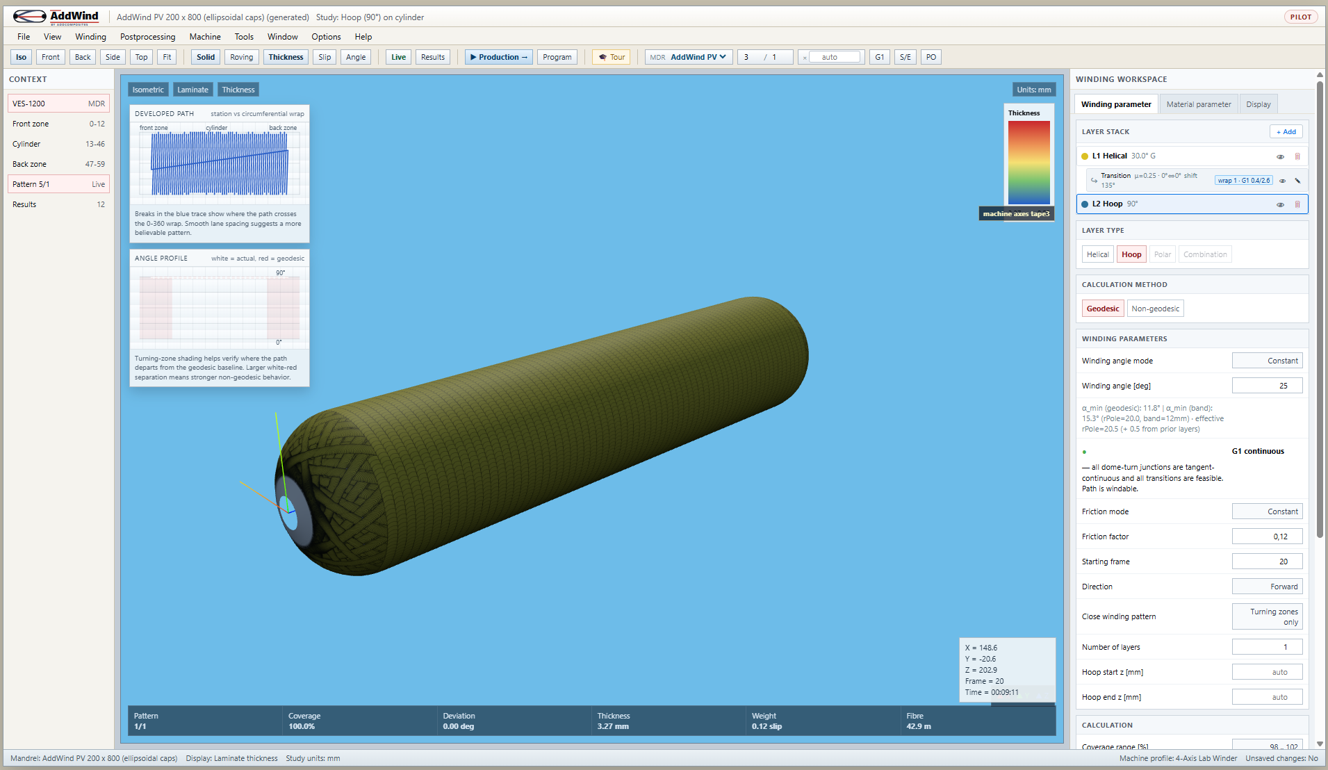
AddWind's Thickness mode is the right tool for the dome problem. Three things to try:
- Open the simulator. Wind a single 25° helical layer on the LongTank mandrel.
- Click Front view, then switch to Thickness mode. The dome lights up. Note the thickness ratio between cylinder mid-span and the region just inside the boss — typically a factor of 2 or more.
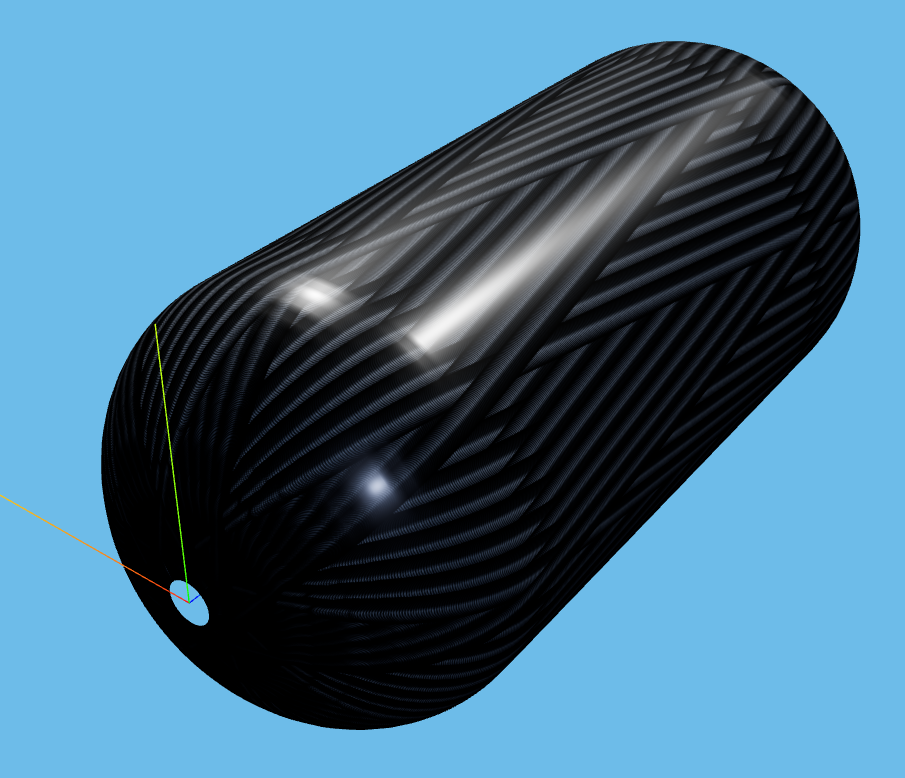
- Add a polar layer (low-angle helical, e.g. 12°) first in the layer stack. Re-check Thickness mode. The polar layer dramatically smooths the dome buildup.
- Open the Layer Stack panel and reorder the layers. Notice how changing sequence changes local thickness and the apparent stack shape.
For a more advanced check, switch to the Slip view in the toolbar. The dome region usually shows high slip values for low-angle layers — that is the warning that the fibre is being asked to deviate substantially from a geodesic to make the wrap. Bring the friction factor down to see how much of the path is actually feasible.
Practical takeaway
For the dome turnaround:
- Design the dome shape first. Use geodesic/isotensoid dome theory as a reference point, then verify the actual dome and boss design with analysis and test.
- Place low-angle or polar-style reinforcement deliberately. If the design uses it, evaluate whether it belongs near the liner and how it affects subsequent helical and hoop layers.
- Use dwells sparingly. Add
dwell frontanddwell backonly when you need to anchor a turn; one dwell at the end of a layer beats four small dwells inside it. - Verify the thickness profile. Use AddWind's Thickness mode at multiple build stages — after the polar, after the first helical, after the hoop — to catch local hot spots early.
- Inspect the boss interface separately. The metal boss geometry, fibre angle at the boss, and seal design have to work together. None of them is purely a winding question.
Next step
You now have the conceptual machinery for the winding job. The final question is how the simulation actually turns into a wound part. Read From Simulation to Machine Program for the path from AddWind's Planning view to a real winder.
Or open the simulator and inspect the dome: https://addwind.addcomposites.com.
References
- Koussios, S. (2004). Filament Winding: a Unified Approach, Chapters 8 and 9 (Dome design, isotensoid profiles).
- Vasiliev, V. V., et al. (2003). New generation of filament-wound composite pressure vessels for commercial applications.
- Azeem, M., et al. (2022). Application of Filament Winding Technology in Composite Pressure Vessels and Challenges — A Review.
- CADWIND user manual — sections on Helical winding parameters (dwell mechanics).
- AddWind internal:
docs/winding-modes-guide.md.
Open AddWind, adjust the winding setup, and inspect the path, laminate and production motion in the same browser workspace.