
From Simulation to Machine Program in Filament Winding
A filament winding simulator becomes most valuable when its output can be checked against real machine constraints and, eventually, passed into a controller workflow. Between the on-screen 3D viewport and the controller that spins the spindle, there is a chain of verification steps — dry-run, motion analysis, post-processing, export. Each step exists because something at that step has historically failed on real machines.
This article walks through the whole chain, using AddWind's Planning → Production → Program workflow as the example.
Why this matters
Winding software fails in three places, in increasing order of cost:
- Geometric infeasibility — the simulator allows a path that the physical machine cannot execute (impossible axis acceleration, payout-eye collision with the mandrel, etc.). Cost: rejected program, half a day lost.
- Process infeasibility — the path is geometrically fine but the fibre cannot actually lay down on it (excessive slip, unanchored turnarounds, dome wrap below the boss). Cost: rejected part, full lay-up restart.
- Silent quality drift — the path is fine and the part is wound, but the laminate properties do not match the design (wrong fibre-volume fraction, uneven coverage, off-angle layers). Cost: failed proof test or, worse, in-service failure.
The simulation-to-program chain is the set of checks designed to catch these failures before a real machine is involved.
The simple explanation
Most winding workflows can be understood as three logical stages, even if individual tools name them differently:
- Planning — design the laminate. Pick mandrel, layer types, angles, patterns, band widths.
- Production / dry-run — play back the plan as machine motion. Verify that the carriage, mandrel and payout eye actually move in a way the real machine can execute.
- Export — write the plan out as a machine-readable motion table or controller-specific program through a post-processor.
AddWind exposes Planning and Production views today. The Program button opens Motion Analysis for the prototype machine model, and export is currently in pilot.
What happens in the real process
In production winding, the path from planner to machine looks like this:
Step 1 — Planner output. A planner produces, at minimum, a synchronised table: for each step i, the mandrel angle θᵢ, the carriage position Xᵢ, the cross-feed Yᵢ, and the payout-eye rotations Bᵢ and Cᵢ if your machine has them. Some production workflows also manage free-length, tension and process setpoints, either inside the winding program or through parallel machine settings.
Step 2 — Post-processor. A post-processor converts the synchronised table into the controller's native format. Different machine vendors use different controller formats and post-processing conventions. The post-processor is where machine-specific limits such as velocity, acceleration and soft limits should be enforced.
Step 3 — Dry run. Before any fibre is loaded, the program is executed on the machine with no fibre. The operator watches for collisions, motion-limit errors, and obviously wrong motion. AddWind's Production view is a virtual motion review for the current prototype machine model. It is not a substitute for a machine dry run on real hardware.
Step 4 — First-article wind. With fibre loaded, the first part is wound carefully, often at reduced speed. The operator watches for slip, lay-down quality, tension excursions. Anything found at this stage feeds back into the planner.
Step 5 — Production winds. Once first article passes, the program is locked and runs at production speed.
What engineers often miss
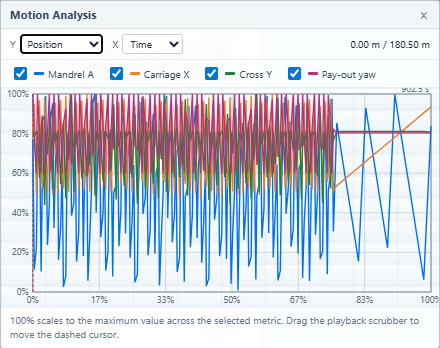
A 3D visualization is not a verification. A path that looks beautiful in 3D can still violate axis acceleration limits, collide with the mandrel, or require a payout-eye orientation the real machine cannot reach. The Motion Analysis chart is the verification — it shows every axis as a time-aligned trace and flags peaks.
Tension is not part of the path. Tension setpoints are a parallel channel of information that has to be exported alongside the path. Forgetting tension export means the machine runs the path at whatever tension was last set, which is usually wrong.
Dwells are real motion. A 360° dwell at a turnaround is a full mandrel rotation with the carriage stopped, but the controller has to know about it. Skipping the dwell in the export means the machine accelerates straight through the turnaround, slipping the fibre off the dome.
Layer transitions are non-trivial. Going from a hoop layer to a 25° helical involves a short non-geodesic transition segment — a third winding pattern between the two layers. Most planners compute this for you, but some require the operator to add it manually. Verify it is in the export.
How AddWind helps visualize or check this
AddWind's two stages — Planning and Production — map directly onto the workflow above.
- Planning stage — design the laminate using the layer-type panel, the N/S/cycles toolbar, and the Layer Stack view.
- Click ▶ Production →. The design locks; the viewport shows the carriage and payout eye in motion.
- Click Program. The Motion Analysis chart opens. Read off peak carriage velocity, peak free-length angle swing, and any abrupt acceleration events. These are the values your machine has to deliver.
- Use the dry-run controls to step through the program at any speed, including frame-by-frame near the turnarounds.
For pilot users, the goal is to export a synchronised motion table that can be adapted through controller-specific post-processing. Controller-specific export integration is the focus of the current pilot phase.
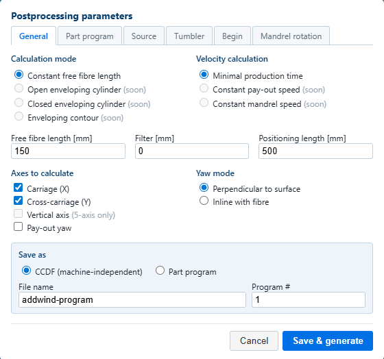
> Note: AddWind today is a planning and simulation tool. Real-machine program export is in pilot — early users get hands-on support to integrate with their specific controller. If you want to participate, the feedback page is the right starting point.
Practical takeaway
When you evaluate a winding software (or a winding software upgrade), look for these capabilities, in order:
- Visible motion analysis — does the tool show you the time-aligned axis traces, or just a 3D animation? A 3D animation alone is not enough.
- Explicit dwell modelling — can you add and inspect dwells at layer endpoints and turnarounds?
- Layer transition modelling — does the tool draw the non-geodesic segment between layers, or does it assume the operator handles it?
- Vendor-neutral export — can the tool emit a synchronised table that you can post-process for your controller, or is it locked to one vendor?
- A real-machine pilot path — does the vendor offer hands-on integration, or do you have to figure it out yourself?
A tool that handles all five reduces the gap between screen and machine, but real-machine commissioning still requires controller integration, dry runs and first-article validation.
Practical CTA
AddWind is in active pilot for the simulation → machine program chain. If you are building or commissioning a filament winding line and you want a hands-on partner on the planner-to-controller step, the fastest way to start is the feedback page:
https://addwind.addcomposites.com/feedback
Tell us your machine, your part, and your timeline. We will respond with a pilot scope.
References
- Koussios, S. (2004). Filament Winding: a Unified Approach, Chapter 10 (Machine kinematics).
- CADWIND user manual — sections on Combination winding (layer transitions), Helical winding (dwells), and Post-processing.
- Quanjin, M., et al. (2018). Filament winding applications.
- Sorrentino, L., et al. (2019). Robotic filament winding.
- AddWind internal:
docs/winding-modes-guide.md,docs/design/14-layer-transitions-plan.md.
Open AddWind, adjust the winding setup, and inspect the path, laminate and production motion in the same browser workspace.